Information and direction to learn the skills that take you from your very first build to Townsville Robot Combat champion — in your weight class and division.
🚧 Heads up — this Knowledge Base is a work in progress. We're actively adding to it, so check back regularly for new guides and detail.
The Foundations
The science behind the smash
A combat robot looks like a toy and fights like a tank — and underneath it is a surprising amount of real STEM. Building one pulls in all four pillars at once: the science of how materials behave under impact and how a motor turns electricity into force; the technology of CAD software, 3D printers and electronic speed controllers; the engineering of turning an idea into a machine that actually drives and survives; and the maths of weight budgets, gear ratios, voltages and centre of gravity. You don't need a degree in any of it — you pick it up one build at a time — but every robot you make quietly teaches you all four.
In practice the journey looks like this: you design and model your robot in CAD, prototype and 3D print the parts, wire up the electronics — motors, battery, speed controllers and a receiver — and then learn to drive and control it under the pressure of a live arena. Each stage is a skill in its own right, and this Knowledge Base is here to help you build them up.
Design Thinking
Design for modularity
Build a robot you can reconfigure between fights, not a one-trick machine.
The best combat robots aren't fixed — they're modular. Design yours so you can swap parts quickly between matches: different armour types (light and fast, or thick and tanky), armour moved to different positions to cover wherever you keep getting hit, and weapon lengths or styles changed to suit the fight. The more options you can bolt on, the more answers you have.
That's why a well-stocked spares box wins events. Carry a few tricks and spare configurations so you can read each opponent and adapt — play to your own strengths and set up to exploit their weaknesses. Struggling against a low wedge? Fit a longer weapon or reposition your armour and roll out a different robot. Adapt to whoever's in front of you and you'll be a real threat in competition.
Prototype fast, optimise faster
Prototyping is the quickest way to dial a design in. Instead of printing a whole robot and hoping for the best, print small test pieces to check the things that simply have to be right — hole sizes, motor and bearing fits, mounting points and tolerances. A ten-minute test print that confirms a motor seats perfectly saves you a ten-hour reprint of the entire chassis. Print, measure, tweak, repeat — that loop is where good robots are made.
Constraints & compromise
Every good robot is an exercise in give and take. Understand these two ideas and the rest of the build makes a lot more sense.
Constraints — the rules you can't bend
A constraint is a hard limit you have to build within — you can't argue with it, you can only design around it. Your weight-class maximum, the PLAstic construction ruleset, the motors and their torque, the plastic types you can print, the size of the arena — these are all fixed. Your job is to make the best possible robot inside them.
Compromise — the give and take
Once the constraints are fixed, every choice is a trade. Spend weight on one thing and you take it from another. Thicker armour means a lighter, weaker weapon. A bigger weapon motor means a smaller battery and less run time. Wide, grippy wheels for control leave no weight for wheel guards — so you put that armour on the front instead. There's rarely one "right" answer.
You can't change the constraints, so you get clever with the compromises. A patient control bot and a brutal spinner can both win — they've simply made different trades with the same weight budget. Learning to make those trades deliberately, instead of by accident, is what turns a parts list into a competitive robot.
Weight Management
Don't get disqualified for being overweight
Every robot is weighed before it fights and must come in under its class limit. Go over — even by a gram — and you don't get to fight. Here's how to stay legal and still hit hard.
Reinforce where it matters, refine everywhere else
Your weight budget is fixed, so spend it where it counts. Reinforcement and refinement is the constant back-and-forth of strengthening the parts that take a beating and trimming the parts that don't. Hollow out, thin down or lighten areas that aren't structural or never get hit — then pour that recovered weight straight back into what wins fights: thicker armour where you take impacts, or denser, tougher plastic prints in the key areas. Same legal weight on the scales, a far harder robot in the arena.
Know your weight before you print
Your slicer can estimate a model's weight right in the slice preview — but only if you tell it the correct filament density. Put the right density value into the filament profile of whatever slicer you use (Cura, Bambu Studio, PrusaSlicer, OrcaSlicer and so on), and the preview weight becomes far more accurate — not perfect, but close enough to plan around before you waste hours of printing. You'll find that density figure on the filament brand's website, usually on the very same product page that sells you the filament, listed in the TDS (Technical Data Sheet). Two minutes of setup that saves you a nasty surprise on the scales.
Step 1 — in your slicer's Filament section, click the edit (pencil) icon beside your filament to open its material settings.Step 2 — under Basic information, enter the Density (g/cm³) from your filament's TDS into the Density field.
Step 3 — turn off your Supports and Brims for this part.
Step 4 — slice the model and check the approximate weight.
Step 5 — if this is over your desired weight, return to the slicer and change infill, walls or other settings to remove weight, then repeat step 4. Once you have your desired weight, go back and add any Brims or Supports your model needs BEFORE printing.
Learn
Educational links
Trusted, beginner-friendly resources from the wider combat robotics community.
Power transmission is an important topic not only for combat robotics, but also for mechanical design. Power transmission refers to using a mechanical connection to transfer power from one location to another.
Gear Ratios
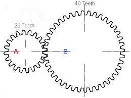
The ratio from A to B would be 2:1
The most important concept relating to power transmission is gear ratios. A gear ratio is a number that effectively approximates the relationship between the input and output of a single stage of a power transmission system. A gear ratio is usually expressed as
tin : tout = rout : rin = nout : nin ,
where t represents a number of turns about the shaft, r represents the radius of the object where contact occurs, and n represents the number of teeth on a profiled surface. This equation can be used to explain the relation between gears, pulleys, sprockets, and a whole variety of other mechanical devices. Gear ratios for multiple stage systems are the product of the individual gear ratios of each stage. Gear ratios change both the torque and the speed of the output relative to the input following the following equations
τout = (nout / nin) ∗ τin
ωout = (nin / nout) ∗ ωin
where τ is the torque transmitted around the rotational axis of the shaft and ω is the rotational speed of the shaft. A gear reduction is a gear ratio where the input shaft spins faster than the output (tin > tout).
Common Power Transmission in Robotics
This section will focus on translating rotational motion between a motor and a driven load. There are five good ways to do this, and this section will break down how each of these ways works, and then compare them in different loading scenarios. Each of these methods is suited for different applications, and a table summarizing the differences is shown below:
Drive Type
Input/Output Relation
Configurable Ratios
Protects Motor
Allows Slip
Backlash
Point of Failure
Direct
Colinear
No
No
No
None
Motor or Shaft
Gearbox
Colinear or small offset
Yes
Somewhat
No
Medium
Gears or Output Shaft
Gear
Offset parallel
Yes
Yes
No
Small
Smaller Gear or Motor Shaft
Belt
Offset parallel
Yes
Yes
Sometimes
Large
Belt or Pulley
Chain
Offset parallel
Yes
Yes
No
Medium
Chain or Motor Shaft
Features for Power Transmission Methods
Direct Drive
Direct drive is used in applications where the load does not experience any impact forces. In applications where direct impacts are expected, motors used for direct drive can be reinforced with larger drive shafts. Direct drive systems are generally smaller than other power transmission methods (the motor can be partially inside the driven load), but they lack the strength and robustness of other solutions and do not allow for any gear reductions between the motor and load.
Gearboxes
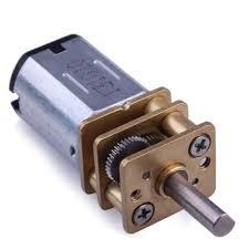
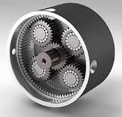
N20 Motor with GearboxPlanetary Gearbox
Gearboxes are attached to the end of a motor and provide a reduction in speed or torque between the input and the output. Gearboxes are mostly used to reduce speed and increase the torque applied to the output but can be designed for any ratio to be achieved. Because the output on most gearboxes applies more torque than the input, the output shaft is generally larger and stronger than the input shaft. Most small, hobby sized motors have output speeds in the 10,000 rpm range. A lot of applications that motors are used for require more torque than these motors can provide and need the motor to spin at a fraction of its maximum speed. Gearboxes are added to these motors to reduce the maximum output speed and increase the torque at the output. Motors are commonly sold with gearboxes attached and are called gearmotors. These motors are sold with either a standard gearbox or a planetary gearbox. Planetary gearmotors can achieve higher reductions in a smaller, more durable package. Gearmotors can also be used in series with other power transmission methods but are the most space-efficient ways to implement high reductions. In combat, drive motors are generally gearmotors or brushless motors coupled to planetary gearboxes. These motors are also used in weapons of non-spinner weapons including saw arm actuation and lifter arms.
Gear Drive
Gear Drive
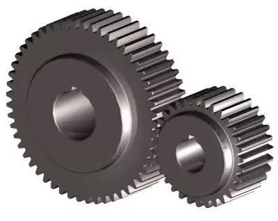
Gear drive is different from using a gearbox because the output shaft is offset from the input shaft. A gear drive stage connects the input and output shaft with two gears. Gear drives are used for reductions over a small distance, as the distance between the two shafts is the sum of the two gears’ pitch radii. A pitch radius is a the most important parameter when designing gear drives as the shafts must be positioned so the two gears’ pitch circles are tangent at the point of contact. Gears are designed to perform optimally at this condition, which makes it hard to change out gear ratios once shaft locations are fixed.
In combat robotics, gears are generally used to drive non-spinner weapons that want a small reduction and little to no slip between the motor and the driven load. Gear drives can increase the torque that a motor can provide for weapon arms on lifter, saw, or hammer robots. Gear drive is not a common drive method for spinning robots because there is slip integrated into the system. When a spinner weapon goes from spinning at a high speed to stopping spinning quickly it can cause a lot of stress on the motor. Without some sort of slip in the driving system (to stop the motor from stopping so fast) parts of the motor can break or the motor can induce a large current in the electronics driving it, potentially breaking the driving ESC.
Belt Drive
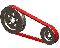
Belt drive is used to connect two shafts with a gear ratio that are spaced far enough away that gear drive is not effective. Belt drives utilizes a belt (lmao) to transfer torque between two pulleys. Belts are by far the most common method of power transmission in insect weight robots, especially in spinning weapons. Belts are durable, simple, and can allow for slip between the pulleys which can protect the drive motors from damaging accelerations. There are several types of belts that are common in combat robotics including V-belts, round belts, and timing belts.
V-Belt
V-Belt Drive
V-Belts are commonly used in weapon drive systems. Because they have no teeth on them, they rely entirely on friction to transfer power between the drive and driven pulleys. The largest advantage of using v-belts is their tendency to slip under high torque situations. When a weapon impacts a target and slows down quickly, a v-belt will isolate that acceleration from the motor and protect it. This gives robot increased reliability but has a few downsides. First, a v-belt will sometimes slip when starting up, due to improper tensioning or a very powerful motor. This increases the spinup time for the driven load. Another problem with V-belts is that they heat up and stretch when they slip often. Powering a V-belt pulley when the loaded pulley is not able to spin will likely heat up the belt and stretch it to a point of failure. V-belts also need to be properly tensioned between the input and output in order to work effectively. The best v-belt systems incorporate some sort of spring driven active tensioner which keeps the belt stretched tight against the pulleys. If the belt is replaced often enough and the pulley separation is calculated correctly in the design, it is possible to use v-belts without a tensioner as long as they are often replaced.
Round Belt
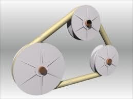
Round Belt Drive
Round belts are similar to v-belts in the way they transfer loads. They have similar pros and cons but have one major difference. Round belts are purchased in bulk tubing lengths, then cut to length and fused to create a single belt. V-belts are purchased at the length that they will be used at, and as such are stronger than round belts in tension. This means that V-belts will be better suited for any large torque applications. Round belts are commonly used because they are cheaper than other belt styles (belting is bought in bulk material and is not specific to the application) and it is simpler to apply in a pre-made design as there are no external tensioners or complex math needed. Round belts are commonly used in robot drive applications, connecting two wheels to a motor for four wheel two motor drive.
Timing Belt
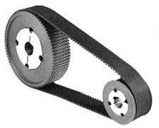
Timing Belt Drive
Timing belts are flat belts that have teeth protruding off the surface of the belt. These teeth allow the belt to transfer large torques between the two pulleys but do not allow for any kind of slip. Timing belts can be used to power both weapons and drive on insect scale robots, although they are not used to power weapons at larger weight classes. Timing belts are easier to implement as they often work without tensioning systems, and they can provide a faster spinup in a weapon system or more accurate movement in a drive, but they do not protect the drive motors which can lead to failure.
An Introduction to Bearings
Anyone who has designed a robot from scratch has used bearings of some sort. Low power rotating shafts can spin in place through a hole without too much of a problem but increasing the speed of the shaft can create drastic problems with efficiency loss. The solution for this problem is the use of some sort of bearing. Bearings support a shaft and decrease friction. While most traditional bearings support rotating shafts, linear bearings allow for support in linear motion. The three main types of bearings used in combat robotics are ball bearings, needle roller bearings, and bushings.
Ball Bearings
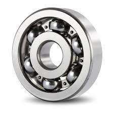
Radial Ball Bearing
Ball bearings are the most commonly used bearings. They use steel balls top reduce the friction between the outer and inner races. These bearings are commonly used as they are very cheap and are usually around 99% efficient. Ball bearings are also able to withstand both axial and radial loads. Ball bearings will have both a maximum speed rating as well as radial and axial load ratings on the spec sheet when bought from a manufacturer. For use in combat robotics, these bearings are often found in both the drivetrain and the weapon. When used in the weapon, these bearings can fail if one of the races cracks or one of the balls shatter upon a big impact. If this happens, the bearing will lock up and be noticeably harder to turn, and usually makes a scratching or crunching noise when turned. One important consideration when implementing these bearings is to keep the spinning and stationary hardware from touching the opposite races. If a shaft is spinning in the inner race, and the outer race is fixed, then whatever is connected to the shaft should not be able to touch the outer race of the bearing, and any fixed hardware should be located away from the inner race. This decreases friction and can stop the bearings from binding up or overheating.
Needle Roller Bearings
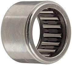
Needle Roller Bearing
Needle roller bearings are similar to ball bearings but use cylindrical rollers instead of balls to decrease friction. These bearings have the downside of being hard to implement and more expensive than ball bearings, but they offer several performance advantages. They also do not usually have an inner race, as the rollers directly touch the shaft, which decreases their size drastically. This makes them easier to use in tight spaces and can decrease the size of the object that they are spinning. The only problem with needle bearings is that they are not capable of resisting axial loads. This means that they need to be used in conjunction with some sort of thrust bearing or bushing that is able to mitigate the axial loads. Needle bearings are more complex and more expensive to properly implement, but they can provide the reliability that is essential for winning combat robots.
Bushings
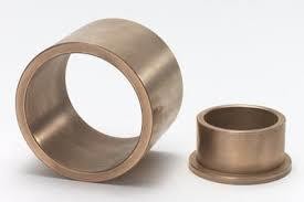
Bushing | Flanged Bushing
Bushings allow for rotational motion without any internal moving parts. Bushings are generally made from oil impregnated copper, and they release the oil as lubricant as they are used. Bushings are not commonly used in combat robotics, as they are less efficient that ball and needle bearings, and cannot withstand high speeds, but they are worth looking into for applications that need to withstand high loads in small spaces at low speeds.
DC Motors
DC motors are motors that draw their power from a constant DC voltage power supply. Most small, non-industrial motors are DC motors. There are two distinct types of DC motor: brushed and brushless. DC motors run current through loops of wire to induce magnetic fields, then repel against permanent magnets in order to create motion. Motors usually have very small diameter wires and can fit thousands of loops of wire inside the motor to improve the power in the motor.
Brushed DC Motors
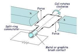
Brushed DC Motor Diagram
Brushed DC Motors are the cheaper of the two types of motor. They also are much easier to control, as they will spin continuously with a constant voltage input. Brushed motors are named after the brush contacts that change the voltage inputs to each motor wire coil.
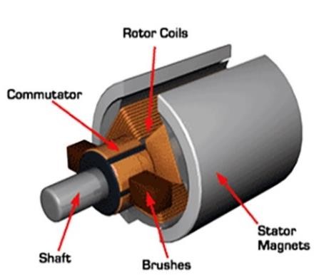
Brushed DC Motor Internals
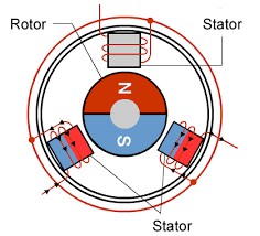
A voltage is applied across two (or more) brushes in the motor. These brushes touch the commutator, which is connected to the ends of the loops of wire. As current flows through the wire, it generates a magnetic field that repels against the permanent magnet mounted on the edge of the motor. As the motor starts to move, due to the force from the permanent magnet, the brushes lose contact with the commutator sides, and the momentum of the motor carries it forward until it contacts the other side of the coil. This then inverts the magnetic field produced in the coil, which continues the motion of the motor.
PWM Signal
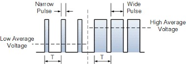
Electronic Speed Controllers are unable to directly dictate the speed of a brushed motor. Lowering the voltage applied to the terminals limits the amount of torque that the magnetic field generates, which limits the maximum speed of the motor. Speed controllers are able to keep full torque and control the speed of the motor with PWM signals. PWM signals keep the voltage at the maximum for a portion of a cycle, then lower the voltage to 0 for the rest of the cycle. The duty cycle of a PWM signal is the percentage of the cycle where the signal is high. Using PWM signals, the motor can use maximum torque while changing the maximum speed of the motor. In order to keep the speed of a motor relatively constant, most speed controllers operate at a frequency of more than 1kHz, which means that a single cycle takes less than 0.001 seconds. This allows for smooth speed control of motors.
Brushed motors are a cheap and easy to implement. Most brushed motors are wound to spin at thousands of rotations per minute and are attached to planetary gearboxes to reduce the speed and increase the torque output. Coupled with the right gearbox, brushed motors are available for almost any speed range needed. Brushed motors are often used in combat robots as drive motors or to power non-spinning weapons.
Brushless DC Motors
Brushless DC Motor Diagram
Brushless DC motors are more complex to control than brushed motors, but they have a much greater power density. These motors have three windings and keep the windings stationary to spin the permanent magnets. These robots require complex speed controllers that apply voltages to the coils in the stator to keep it spinning. One advantage that these motors have over traditional brushed motors is that they will always be able to use 100% of their available power, no matter what speed they are spinning at.
Brushless motor electric speed controllers (ESCs) change the input voltages to each of the three wires to rotate the motor. In order to efficiently drive these motors, they need some sort of feedback to tell the current position and speed of the rotor. There are three types of feedback that ESCs can use. Many hobbyist motors that are used for drones don’t have any type of sensor onboard. These motors are controlled by speed controllers that measure the back EMF generated by the dormant coil and use that measurement to estimate rotor speed and position. This control method is very cheap, as it does not require any sensors, but does not work well at low speeds. Motors controlled through this method lack low speed torque and can sometimes have cogging issues when trying to spin up to speed. More expensive motors use either hall sensors to provide feedback about the position of the magnetic field, or rotary encoders to provide precise position feedback. Not only do these motors cost more, but their controllers are more expensive too. The tradeoff for the complexity and cost is that they have full power at even 0 speed. These motors are generally used in slow applications, such as a robot’s drivetrain.
Inrunner and Outrunner Motors
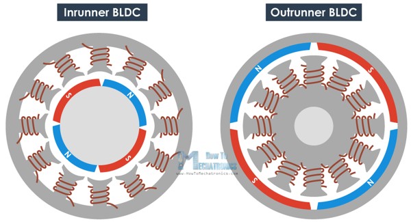
There are two major types of brushless DC motors. Inrunners have the magnetic ring on the inside of the motor, and stator is located around the shell of the motor. These motors are commonly sensored and used in hobbyist boats and cars. Outrunners have the magnet ring mounted to the exterior frame of the motor, and the coils of the stator are mounted inside. Outrunners are generally air cooled and are commonly used in drones and planes. Both of these motors come in a variety of sizes and power ratings. Outrunners are also usually lighter and smaller than inrunners.
Hobbyist brushless outrunner motor sizes are formatted as **## where the ** is the stator width and ## is the stator length. These numbers are not the external sizing of the motor but they do effect the torque and power that the motor is able to produce. These motors also have a KV rating that conveys the maximum speed as a ratio of the input voltage. KV ≈ rpm/volts at no load.
A more detailed explanation of how brushless DC motors and speed controllers can be found here: howtomechatronics.com
Design for Manufacturing Tips and Tricks
The ability to design a part for a specific manufacturing process is an important skill for an engineer to develop. The following section describes some of the following manufacturing methods and gives some tips and tricks I have learned when designing parts for those fabrication methods.
Waterjet Cutting
Waterjet cutting is a 2D fabrication process that uses high pressure water combined with some sort of abrasive element to cut through materials. Waterjets are used to cut anything from plastics to hardened steel. A waterjet usually accepts a DXF file which an operator converts to a toolpath.
Waterjets are unable to do partial cuts into materials. This means that any cuts for a waterjet need to be through the whole part and not partial “pockets” in the part. Additionally, any countersinking or counterboring for screws will need to be done after fabrication.
Waterjets take several seconds to pierce through the material for each cut, reducing the number of cuts by connecting holes will decrease fabrication cost.
Waterjets have a cutting diameter is around .040 inches, which prohibits smaller details.
Waterjets will leave draft on the parts, so tight tolerance area will need to be finished afterwards. Undersizing holes will allow for a post-fab operation to reach the correct size.
Laser Cutting
Laser cutting is another 2D fabrication process that uses a high power laser to cut through material. Hobby-grade laser cutters are able to cut some plastics and wood, but high powered industrial lasers can cut anything from aluminum to hardened steel. A laser cutter also uses a DXF file.
Laser cut parts are unable to do partial cuts as well. Any cuts must be through the entire part.
Laser cutting does not leave draft on parts, so there is not as much of a need for post-fab operations. Bearing and press fits should still be machined post-fabrication for precise fits.
Laser cutters have cutting diameters of less than 0.001”, which allows for detailed cuts.
Plasma Cutting
Plasma cutting is yet another 2D fabrication process that uses an electrical arc to cut material. Plasma cutting is much cheaper than laser or waterjet but has some large restrictions. Plasma cutters can only cut through electrically conductive materials and are much less accurate than laser and waterjet cutters. Plasma cutters also leave rough edges that must be ground post process.
Plasma cutting is good for rough shapes that do not need to be very precise, as all cut surfaces will need to be ground down to shape.
Plasma cutting is good for welded assemblies, as connections will be ground before welding
Plasma cutting is not good for thick material, or for hardened materials, as plasma cutting is a heat generating process, and will destroy the heat treatment on the material.
CNC Machining
CNC Machining is a 3D milling process where a spinning cutting tool removes material while following a computer controlled path. CNC machining is complex and takes a long time to learn but can create accurate parts with complex shapes. CNC Machines are capable of cutting, pocketing, facing, and more operations. CNC machines require a camming software to program their movements to cut a shape from a stock material as well as compatible 3D model.
Because all internal cuts are being made by an endmill, it is very complicated to make internal edges without fillets. Adding fillets can decrease the complexity and time by magnitudes.
When designing a part for a CNC machine, try to think about how many tooling changes the part will need. If internal pockets have relatively small radii, it will take multiple tools to efficiently create the pocket. Instead, try using a larger internal radius.
When designing a part, try to limit the setups that are required. Every hole or pocket will need to be cut from a setup perpendicular to the hole, so limit geometry from new directions.
When designing a part, consider how it will be held during cutting operations. Complex parts may need extra holes added to mount the piece to a fixture, which will also need to be made.
When designing a part, consider how the machine will zero itself between setups. Add edges perpendicular to the machine axes to allow for easy zeroing.
CNC Routing
CNC Routing is a 2.5D machining operation. It uses a spindle and endmills to remove material from the stock like a CNC machine, but it generally uses only a single setup for its work. CNC routers generally are used to cut soft materials including wood, plastics, and sometimes aluminum. CNC routers require a camming software to generate toolpaths from a part model similar to CNC machines.
Because all internal cuts are being made by an endmill, it is very complicated to make internal edges without fillets. Adding fillets can decrease the complexity and time by magnitudes.
Design your part to minimize the amount of post processing needed by limiting features perpendicular to the cutting plane of the machine.
Cut weight from parts without sacrificing much strength by cutting pockets inside the parts while leaving ribs along major loading paths to retain strength and rigidity.
3D printing (FDM) (Filament Based)
3D printing is a 2.5D additive manufacturing process. Printers deposit material layer by layer which stack up to create a finished part. These printers are great for rapid prototyping and fast fabrication and print parts from a variety of plastics. They will never be as strong as a part milled from solid stock, but when printed under perfect conditions, they can come close. 3D printers use a slicing software to generate a toolpath from a STL model of the part.
3D Printed parts are weakest in shear loading perpendicular to the extruding head’s direction. They also cannot print overhangs greater than 45 degrees without support material. Design your part with the printing orientation in mind in order to minimize overhangs and keep the part strong in its loading directions.
Often it is not worth pocketing a 3D printed part, as using a smaller infill amount can sometimes increase the strength of the part while also decreasing the weight.
Holes that are being printed perpendicular to the extruder will often need some sort of post-processing to remove the support material from inside the hole.
3D printed parts tend to expand slightly, so make sure to undersize external features or oversize internal features for tight tolerance fits.
Utilize tapered heat-set insets or embedded nuts for load-bearing threads.
Sometimes it is worth printing a part as two separate parts that press together to minimize support material. Adding a 45 degree chamfer to overhanging edges also improves prints.
Combat Robot Materials
One of the hardest decisions for inexperienced builders to make is what materials to use for each part. This section of the handbook will try to help with that choice by providing some insight into common materials for combat robots.
3D Printed Plastics
3D Printer Filament Comparison
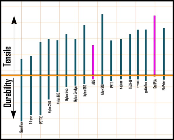
PLA + PLA is one of the easiest to use 3D printing materials. It is effective without humidity and temperature control and can be printed without a heated bed. PLA is very brittle when compared to the other filaments and is not recommended for combat applications.
ABS ABS is a strong and ductile filament that is much harder to print. ABS shrinks as it cools which can leave parts deformed after printing which makes a heated bed and enclosure a necessity. While ABS is a better filament for combat than PLA, there are even better filaments that are much easier to work with.
PETG PETG is described as a material that combines the performance of ABS with the ease of printing of PLA. It is strong and ductile and has very little warpage or other printing issues. PETG is a good filament for combat robotics but is not used at the highest levels.
Nylon and Derivatives (Alloy 910, Nylon X, Nylon G) There are many types of filament that use nylon as the base. Nylon filaments are more complex than the other materials, and are often found with fibers embedded in the material for added strength. Some of the most used nylon derivatives for combat robotics are listed below:
Alloy 910 is an engineered plastic to be as close to be good all around for engineering uses.
NylonG has glass fibers embedded in the material to improve the durability of the part.
NylonX has carbon fiber strands embedded in the filament to improve the strength.
Onyx has carbon fiber strands and has remarkable flexural strength.
Engineering Plastics
HDPE (High Density Polyethylene) HDPE is a wear resistant high strength plastic that can be bought in sheets. This material has a great strength to weight ratio and is surprisingly cheap. It has excellent impact resistance and is uses in combat robotics as a frame material or as ablative armor.
UHMW (Ultra High Molecular Weight Polyethylene) UHMW is slightly stronger than HDPE but is much less rigid. While this improves the material’s impact resistance it makes it harder to use effectively. UHMW used for frames needs to be thicker than HDPE to prevent any unwanted flexing of the frame. Many successful robots have UHMW frames with internal pockets to reduce the weight while keeping the frame rigid and increasing the strength.
Aluminum
6061 Aluminum 6061 Aluminum is the most commonly used aluminum alloy. It is easy to machine but is softer than many other metals. It is also cheaper than many other types of aluminum. 6061 can be used for any part of the robot except for the impactors on a weapon. Many teams design frames or wheel hubs or weapon hubs from aluminum, but using aluminum as an impactor on a weapon will lead to very quick wear.
7075 Aluminum 7075 Aluminum is both harder and stronger than 6061 aluminum. It is also more expensive and harder to machine than other Aluminum alloys. It is commonly used in the same applications at 6061 but specifically is used in parts that see high loads, such as weapon supports.
Steel
4140 Steel 4140 steel is a chromoly steel that exhibits excellent hardenability and a good balance of ductility and strength. This material is commonly used in wedges in lower weight classes and can be heat treated with a blowtorch. Welding 4140 is not recommended as it is very susceptible to cracking during the welding process.
S7 Tool Steel S7 tool steel is a very shock resistant hardened steel. It is generally regarded as one of the best materials for robot weapons and is used for weapons where more than a profile is needed. S7 tool steel is shipped out in its annealed form, which makes machining easier. After machining, the steel must be heat treated to restore its hardness and impact resistance. This makes this material more expensive for most builders, as heat treating steel requires particular equipment that most builders do not have. S7 offers the most benefits for machined asymmetrical drums but can be used in any weapon application.
AR 400 and 500 (Hardox) AR steels are abrasion resistant steels that are generally used for shooting targets and armored vehicles. The number designation after the AR stands for the hardness of the material, harder materials are more abrasion resistant and stronger. AR steel is sold in a pre-hardened condition and is very tough to machine. The most common ways to shape AR steels is using a waterjet or a fiber laser. While these manufacturing methods are expensive, they are much cheaper than having a S7 weapon machined and heat treated and do not sacrifice much in the result. These materials are commonly used for spinning weapons but can also be used as wedges and, at higher weight classes, frames.
Titanium
The most common titanium for combat applications is grade 5 (6AL4V). Titanium offers high strength at a lower weight than many steels found above. It is very hard to machine compared to other materials on this list. Titanium is generally found on combat robotics in weapon shafts, wedges, frame materials, and can be used as a weapon for the smallest scale robots (usually antweights and lighter).
Carbon Fiber Sheet
Carbon fiber sheet is made up of layers of carbon fibers, laminated together. It has a strength to weight ratio of almost 10 times more than alloy steel. The only problem with carbon fiber is that it is very brittle. Some combat teams use carbon fiber for top and bottom plates, but it is to brittle to repeatedly withstand direct contact with weapons.
This Knowledge Base will keep growing — build guides, design tips, slicer settings and hard-won lessons from the arena. Got something you want us to cover? Tell us.